 |
 |
||||||||||||
|
Home : Introduction |
|||||||||||||
 |
|||||||||||||
|
Introduction |
Follow us on
Discuss us on
Watch us on YouTube
Email us at UltraDark mike@ultradark.com
Get our code at GitHub |
||||||||||||
|
The Matrix Modeling Language
Matrix is the abstract modeling language of the Analysis Design Matrix and has been developed from the graphical Shlaer-Mellor Method, PLASMA*PARSEC, ASL, C and Ada.
A free State-of-the-Art Matrix Model Compiler that crystallizes a simpler, more concise version of Shlaer-Mellor's original method is available now. This is the first of a range of Model Compilers that will be developed using our Matrix Technology for various software architectures and programming languages.
With a textual language such as Matrix, model development is often faster due to easier refactoring, merging, differencing and configuration management. Also, the ability to search makes the whole model more accessible, especially for the deeper action language statements.
Ultimately, Matrix is a Thought Tool for assisting the analyst to organise, document and make real the results of the thinking process by way of generated code.
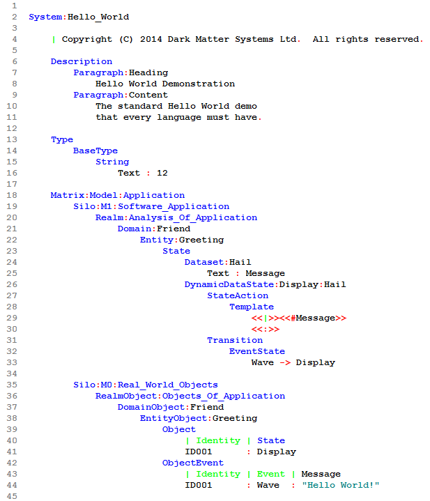
The best way of exploring a new language is to see a small but complete example and work through it step by step. We present a model based on the simple and well understood Hello World! program below: |
|||||||||||||
|
|
|||||||||||||
|
The key to understanding the Hello World! model lies in the domain called Friend (line 21) and the single entity named Greeting (line 22). Greeting declares one state (line 26), one event and a single transition from the state (line 33).
When the model executes, a Greeting object is created in the Display state (line 41) and an event named Wave is sent to the object with a Message of "Hello World!" (line 44) which causes a transition out of and back into the Display state (line 33). On entry to the state the single action in the process state action is executed (line 27). The Message received on the event is then displayed by the Template statement (line 28). A full line by line explanation of this model can be seen here.
Matrix is not a "curly bracket and semicolon" language like C, C++ or Java. Matrix is a modeling language not a programming language. The concepts being manipulated in Matrix are different to the concepts controlled in a programming language.
Notice that Matrix employs indentation to structure the language. This is important to how regions are defined (the scope over which statements act over other statements and data).
|
|||||||||||||
|
Model Compilers, Applications and the Matrix Process |
|||||||||||||
|
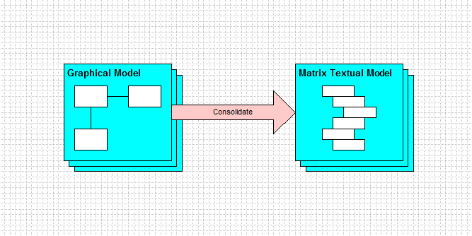
We always recommend drawing out the system to be created using a graphical tool first. This helps to visualise what the components at different levels are and how they fit together. We suggest using the Matrix notation since it has a complete and meaningful mapping to the Matrix language.
Converting a graphical model to a text model should be a process of consolidation. Usually, Entity Relationship and State Transition diagrams are drawn. Drawing out Process Flow diagrams is not considered worthwhile as this is best done in Matrix code.
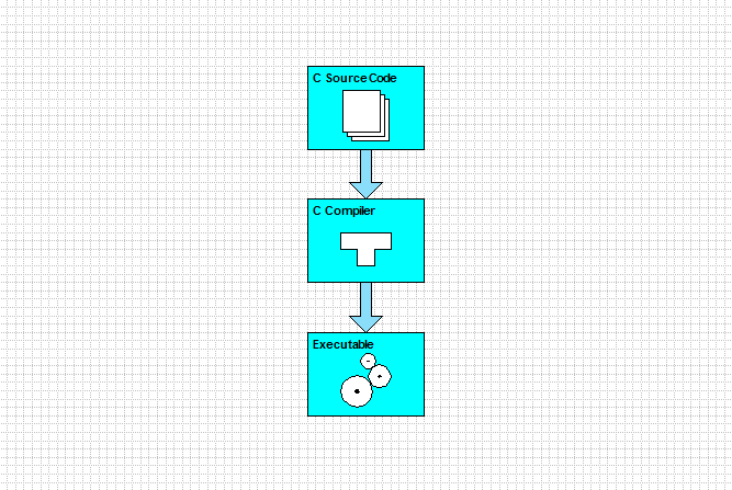
In the typical software development process a programmer writes source code in a programming language which is compiled into an executable that runs on a computer. The code will have an implicit software architecture embedded within it and if another architecture or language is wanted then the entire program has to be rewritten.
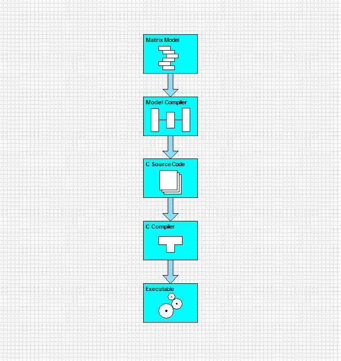
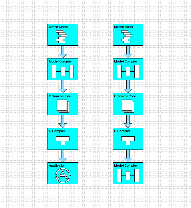
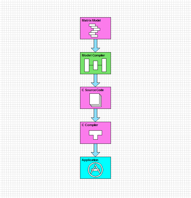
In the Matrix software development process the source code is automatically generated from an implementation independent Matrix model by the Model Compiler.
The Matrix code must be free of implementation details because the implementation such as target language and architecture is added later by the Model Compiler during the process of code generation.
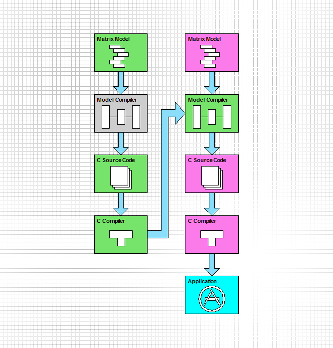
If a Matrix model is that of an application then an application is generated. If the model describes a Model Compiler then a Model Compiler is generated. The software development process for both is identical.
A key point is that the application's language and structure is defined solely within the Model Compiler and this is true when the application is itself a Model Compiler.
This means that the generated Model Compiler's functionality is independent from the host Model Compiler's functionallity. So, a host Model Compiler which is written in C (or any other language) can generate a target Model Compiler which is designed to generate Java (or any other language).
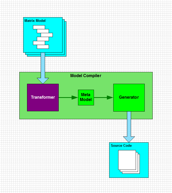
Matrix Model Compilers have three components. The first is the Transformer whose purpose is to parse the Matrix code for syntax errors and to compile the model whilst checking for semantic errors.
The output of this process populates the second component, which is confusingly named a Meta Model. From a Model Compiler constructor's point of view the Meta Model is just a number of record structures or database tables.
However, from the Model Compiler user's point of view it is indeed a Meta Model. The confusion arises from the fact that the Model Compiler creator regards the Model Compiler as an application, whilst the Application writer regards the Model Compiler as a Model Compiler for their application!
The third component is the Generator. Its job is to take the contents of the Meta Model and to produce the source code by a process known as Translation. The Generator is constructed from models that describe the software architecture and code structure of all the applications that it generates.
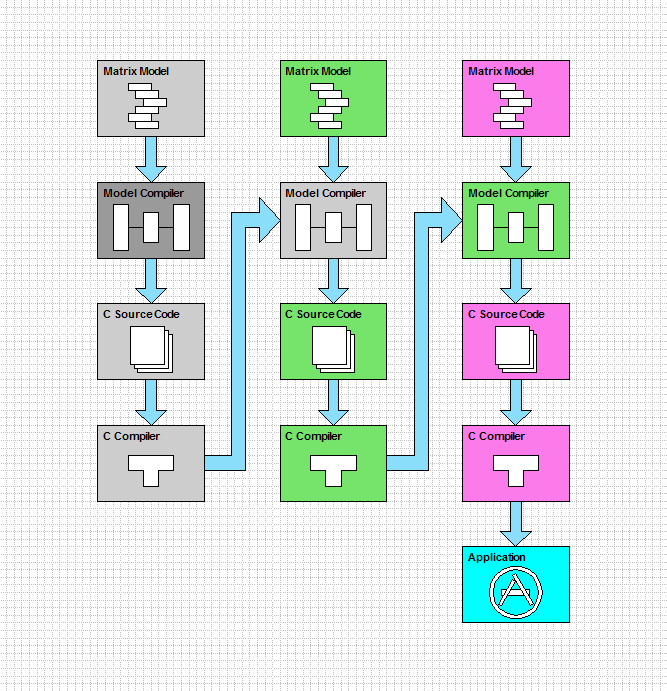
Seen in its correct context, a Model Compiler exists on the level above the application model it compiles. According to the Matrix Analysis Diagram, a Model Compiler is defined at the meta model level, M2 and applications are defined at the model level, M1.
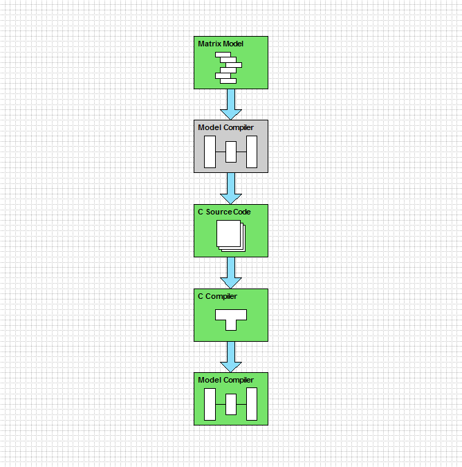
Of course, a Model Compiler that is used to compile an application must itself have been compiled by a Model Compiler that exists at the Meta Meta Model level, M3.
The Model Compiler's Model Compiler does not have to be one that generates C source code as shown here; any language would have been suitable.
This chain of Model Compilers can be traced back to the first Model Compiler called the Bootstrap Model Compiler.
New Model Compilers are evolved from existing Model Compilers and as more Model Compilers are developed existing Model Compilers move to the left so that application models always exist at the model level, M1 and the objects they manipulate in the Real World at M0. |
|||||||||||||
| Copyright © 2017 Dark Matter Systems Ltd. All Rights Reserved. | |||||||||||||
|
|
|||||||||||||


