 |
 |
||||||||||||
|
Home : Matrix Language : Model Examples : Hello World! |
|||||||||||||
 |
|||||||||||||
|
Hello World! Model |
|||||||||||||
|
Introduction
The Hello World! model has a single entity which has one state and one process. The model's purpose is to print "Hello World!". Systems really don’t come much simpler than this.
Overview
The notation on our diagrams is relatively simple. We prefer not to pack too much textual information into a diagram since this is better expressed in Matrix code.
Of course, you are perfectly free to choose any notation you wish including the de facto standard which would perform an adequate job.
We never refer to a diagram as a model because only a complete set of diagrams could be considered to represent a model. Even then, it is still dubious since diagrams simply don’t contain enough detail.
All entities exist as part of a domain and all domains exist as part of a realm. See the section on the Analysis Design Matrix Diagram to learn more about realms and how they fit into silos. For more information about the notation used in the diagrams see Matrix Notation.
The Hello World! model does not require the EventContext or ImportEvent statements since its only event (Wave) is internally generated by an ObjectEvent statement.
Model Walkthrough
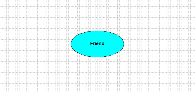
Below is the Domain Bridge Diagram (DBD) for the Hello World! model expressed in our own graphical notation. It shows just the single domain called Friend. If the model had more than one domain we would also draw the bridges between them. The Shlaer-Mellor Software Architecture domain is never shown on this diagram.
Realm:Analysis_Of_Application
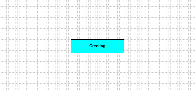
Below is the Entity Relationship Diagram (ERD) also in our own notation (not to be confused with ERDs from years gone by). We name this diagram an Entity Relationship Diagram because it shows entities and relationships, which are the two most important features shown on this type of diagram:
Domain:Friend
If the entity named Greeting had attributes they would be listed on the diagram in their own compartment immediately underneath the entity title. The type of the attributes would also be shown.
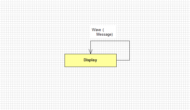
Below is the State Transition Diagram (STD). We name this diagram a State Transition Diagram (along similar principles to that of an ERD) because it shows states and transitions:
Entity:Greeting
This shows the complete lifecycle of the Greeting entity. All of the Greeting objects must follow the same lifecycle. When we refer to the lifecycle belonging to an actual object we talk about its state machine.
Moving back to the Hello World! example, when in the Display state, the state machine waits for an event called Wave and on receipt briefly transitions out of state and returns to the Display state.
On re-entry, any actions (there may be none) that are defined for the state are performed. In fact, it never leaves Display state but this a picturesque way of thinking about how a state machine reacts to an event.
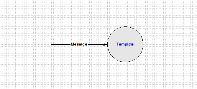
Below is the Process Flow Diagram (PFD) showing the work to be done on entry to the Display state.
Entity:Greeting, State:Display
The PFD shows a flow into the diagram going to a Template action process. It carries an item of state data called "Message" that the process requires to execute. This flow is considered to have both a control flow element and a data flow element. The Template process will print the text in the message and then a newline as can be seen in the Matrix code.
The Hello World! model employs just a small fraction of the statements available in the Matrix Language. Unlike the model in the introduction the model in this section includes an example of the Description and Paragraph statements.
Code Walkthrough
The Hello World! model is an extremely simple example that gives an overview of the basic structure and workings of the Matrix language. Do not be misled by the size of this example for such a trivial application.
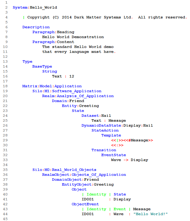
Line 2: The System statement defines a subregion (as all statements do) where it is in scope and simply denotes the start of a system called Hello World. A system may be composed of a number of Matrixes.
Line 6: The Description and Paragraph statements allow the analyst to provide the Model Compiler with informal text about the model which could either be inserted in the generated source code or organised into a document.
Line 13: All entity attributes (they're not needed in this example) and state data items are typed. The Type statement allows a basic set of data types to be declared and constrained. Here, a string type called Text that allows a minimum of zero to a maximum of 12 characters is defined.
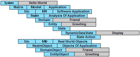
Line 18: The Matrix statement provides an organising structure for Model Compilers, the Application and Real World Objects to be modelled in terms of silos. This is best described by reference to the Analysis Design Matrix Diagram.
Line 19: A Silo statement declares a set of realms at a certain metamodel level (Analysis Abstraction) such as M0, M1, M2 (and so on) which correspond to objects, models, and metamodels respectively. Here, a silo at the M1 Software Application level is declared, which is the level most used by the Business Analyst.
Line 20: A realm is simply a set of closely related domains at the same level of both Analysis and Design Abstraction.
Line 21: The Domain statement declares the name of a domain model that contains one or more tightly associated Entities (sometimes called classes in other modeling languages). Each domain and its entities represent an individual subject matter.
Line 22: An entity is a basic building block of the analysis formalism. It declares various properties such as attribute data and relationships.
Line 23: The State statement indicates the start of an optional lifecycle declaration for the entity. An entity lifecycle defines the sequential states that the entity may progress through when responding to events from outside. The lifecycle defines the individual state machine for all objects of the entity.
Line 24: A dataset declares one or more state data items that a state may receive as part of an event that causes the transition into that state. In other words, a dataset is the data carried on an event to a state. Here, the state data is just a Text string called Message.
Line 26: The lifecycle for the entity called Greeting has one DynamicDataState called Display. The state's dataset is called Hail.
Line 27: The StateAction statement introduces the list of action statements.
Line 28: Templates are fragments of predefined text embedded with directives which appear as a name between the double angle brackets "<< and ">>". The text in a Template subregion is displayed or can be written to a file.
Line 29: The <<|>> directive is a placeholder and not important here. The <<#Message>> directive displays the state data Message string in the appropriate place when the Template text is displayed.
Line 30: The <<:>> directive has the function of displaying a newline. In Template subregions, clarity is improved if this directive is placed at the start of the line.
Line 31: The Transition statement introduces the section detailing how the events to be received by a state machine in this state are to be processed.
Line 32: The EventState statement lists those events that will cause a transition to another state.
Line 33: In this case, the event called Wave (with a dataset called Hail containing state data called Message) will cause a transition into the state called Display which happens to be the state the entity was already in. This has the effect of whenever the Greeting entity accepts the Wave event the string contained in Message is displayed.
Line 35: A M0 Real World Objects Silo describes the initial configuration of some of the entities in the corresponding M1 Software Application Silo when the model starts to execute.
Line 36: The RealmObject Statement refers to the corresponding realm in the M1 Software Application Silo.
Line 37: The DomainObject Statement refers to the corresponding domain in the M1 Silo.
Line 38: Similarly, the EntityObject statement matches the corresponding entity.
Line 39: The Object statement specifies a list of object data for the entity corresponding to its attribute data.
Line 41: The object data consists of an identity literal together with a value for the actual initial state and optional attribute data values. The identity value is not used by the Model Compiler except to match up objects specified in the Object, ObjectRelation (not needed here) and ObjectEvent subregions.
Line 42: The ObjectEvent statement specifies an event together with its event data that is to be directed at the object state machine belonging to the entity Greeting at start-up. The data in the M0 Silo defines the complete state of the system after initialisation and can be viewed to represent a static (attribute data) and dynamic (events in transit) snapshot of some moment in time of the entities in the Real World.
A Code Map is a diagram of the code of a Matrix model. Click on the Code Map below to see the Hello World code.
Expected Output
When the Matrix model is executed under the Simulator with all tracing turned off the following display output is produced in the command prompt window:
Matrix Model Simulator - Learning Edition - Version 1.0.0 Development on THU-02-JAN-2014 @ 11:54:48 Copyright (C) 2014, Dark Matter Systems Ltd. All rights reserved.
Connection established: MATRIX*CORE - Version 0.5.2
$ $ | Hello World Scenario $ $ trace all off $ trace display on $ trace events on $ trace states on $ $ initialise all
Hello World! $ $ $ host pause Press any key to continue . . . $ $ exit
Model Simulation Elapsed Time: 00:00:01
Disconnected from MATRIX*CORE on THU-02-JAN-2014 @ 11:54:49 |
|||||||||||||
|
|
|||||||||||||
| Copyright © 2017 Dark Matter Systems Ltd. All Rights Reserved. | |||||||||||||
|
|
|||||||||||||
