 |
||||||||||||||||||||||||||||||||||||||||||||
|
Home : Matrix Method : Event Transmutation |
||||||||||||||||||||||||||||||||||||||||||||
 |
||||||||||||||||||||||||||||||||||||||||||||
|
The Event Transmutation Cycle |
||||||||||||||||||||||||||||||||||||||||||||
 |
||||||||||||||||||||||||||||||||||||||||||||
|
|
||||||||||||||||||||||||||||||||||||||||||||
|
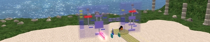
The Event Transmutation Cycle diagram shows how the main analysis diagram types are connected together from a dynamic viewpoint. The diagram is a "Big Picture" view that provides an essential insight into the dynamics of event processing within a model. Specifically, it demonstrates how an external event causes a flow of control through the model and how an event changes from event to progression to control and then back to event as it moves between sectors within the cycle
UML Notation Conversion
Unfortunately, the existing de facto UML notation is sub-optimal for Matrix analysis. Instead, the notation used in the Shlaer-Mellor method has been enhanced for use with the Matrix language. For completeness, the names of the Shlaer-Mellor diagrams have also been included in the table below:
General
The Event Transmutation Cycle diagram provides a more interesting overview of the workings of a model than the usual representation
In diagrams used for code generation, events are the implicit force that drives processing and makes everything work. It is useful to distinguish between two kinds of events corresponding to whether an event is being considered at the external stage or internal stage to the relative model. The external stage concerns events that happen in the Real World that get detected by the system and appear as incoming bridge events.
The internal stage relates to events that appear within the model as tokens. Depending on what sector in the cycle a token is considered it will oscillate between being an event following a relationship pathway, progression on a transition or a control on a data flow.
An oscillating event or token represents a thread of control in a model and ultimately in the source code itself. A single event may go round the cycle any number of times.
Conceptually, an event enters all three diagram types at exactly the same time. This may at first seem counter intuitive but that is only because the diagram types (ERD, STD and PFD) are created and reviwed sequentially.
Each domain has an ERD which represents the entities within it. Domains don't usually exist in isolation but have bridges to other domains. A bridge represents a channel that guides events from domain to domain in either direction.
When something relevant and within the scope of the system happens to a thing in the Real World the event is detected “inside” a low-level service domain which may pass it on to another higher-level client domain through a bridge. After being processed by top level application domains the event continues its journey this time downwards from client to server domain eventually acting on the Real World.
From the ERD viewpoint, an event from a bridge appears as an incoming domain boundary crossing event.
Entity Relationship Diagram
Domain boundary crossing events from a bridge conceptually enter a domain through the Entity Relationship Diagram (ERD). This diagram is the most static diagram of the three kinds used for code generation. Consequently, the ERD is the hardest to understand in terms of dynamic behaviour.
Events are considered to enter at the ERD level because they are directed at entities or more precisely similar objects representing things in the Real World, although since all object data and behaviour are identical it is more convenient to talk of the entire collection or group of objects which is summed up by referring to them as an entity.
When an ERD entity receives an event, it is processed first by that entity. In some cases the event is processed entirely within the context of the entity and the event changes to an implicit (invisible) input on a state machine. In other words, if a relational navigation is not required the event transmutes to a progression on the entity's State Transition Diagram.
The dynamic behaviour of the ERD is demonstrated when considering the case where the event is not handled solely within the context of the initial entity. Before an object can generate and send an event to another object, the sending object must have a pre-existing relationship with the receiving object.
Event generation can only take place when the sending object has the receiving object in context. The context allows it to "know" which object to send the event to. In order to get the receiving object in context the sending object must navigate the relationship between them. From the ERD viewpoint, when events move from entity to entity they are constrained to travel along the paths set by relationships between entities. Relationships prescribe event pathways.
State Transition Diagram
When an event is processed by an entity (or object) it is immediately passed to its own "internal" state machine.
Only certain named transitions are capable of responding to the event. Moreover, the actual transition that will be triggered will be the one that originates from the current state.
Given these two conditions, primed transition and event entry, the event transmutes to a progression which moves from the old state and enters the new state.
An active state may generate its own events which are directed to other state machines.
On entry, a progression causes a state to begin processing by passing the transmutated progression or event to a Process Flow Diagram.
It is often very useful to see where events come from and where they go on a diagram
Process Flow Diagram
An event can undergo transmutation to progression on a State Transition Diagram then back again to an event and then further transmute to an incoming control on a Process Flow Diagram.
The incoming event can appear as a control on a flow (known as a control flow) simultaneously at several points on a Process Flow Diagram.
Where a control flow enters a process the work defined by that process is carried out.
A process may read or write an entity data store, perform a calculation, make a decision or generate an event to another entity within the same domain. An event can also be sent to a bridge.
An outgoing event can take many forms. A bridge always leads to another domain which may enable an event to act on the Real World. For example, it can toggle a bit in memory that causes a motor to turn on or a procedure call that sends an email. |
||||||||||||||||||||||||||||||||||||||||||||
| Copyright © 2017 Dark Matter Systems Ltd. All Rights Reserved. | ||||||||||||||||||||||||||||||||||||||||||||
|
|
||||||||||||||||||||||||||||||||||||||||||||
