 |
 |
|||||||||||||||||||||||||
|
Home : Matrix Method : Matrix Notation |
||||||||||||||||||||||||||
 |
||||||||||||||||||||||||||
|
Matrix Method Diagram Notation |
||||||||||||||||||||||||||
|
Introduction
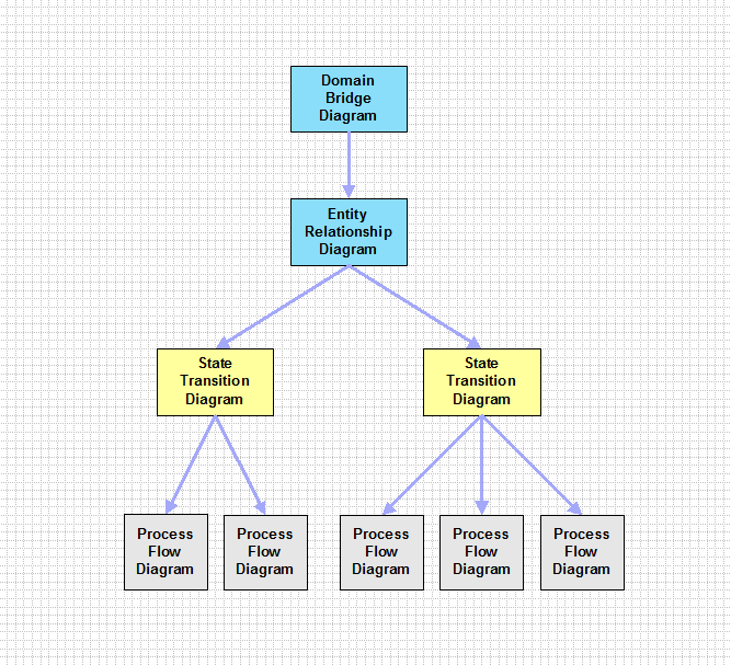
There are just four types of analysis diagram in Matrix:
They are arranged into a hierarchy as shown below:
The Domain Bridge Diagram (DBD) is usually the exploded view of the Analysis of Application realm in the Analysis Design Matrix.
UML Notation Conversion
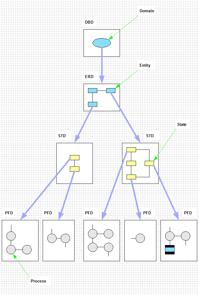
The following chart shows what the four diagram types contain and how they are linked together.
Starting at the top of the chart, the DBD will typically show a number of domains, but for the purposes of explanation we show only one here.
The exploded view of the domain on the DBD yields the Entity Relationship Diagram (ERD). Similarly, the exploded view of an entity on the ERD shows the State Transition Diagram (STD) and finally, the exploded view of a state on the STD gives the Process Flow Diagram (PFD).
Domain Bridge Diagram (DBD)
Domains enforce the separation of concerns by defining subject areas involving closely related entitys. They exist in a client server type relationship with other domains through bridges. Each bridge (not shown) defines the events that may travel (both ways) between the domains.
Entity Relationship Diagram (ERD)
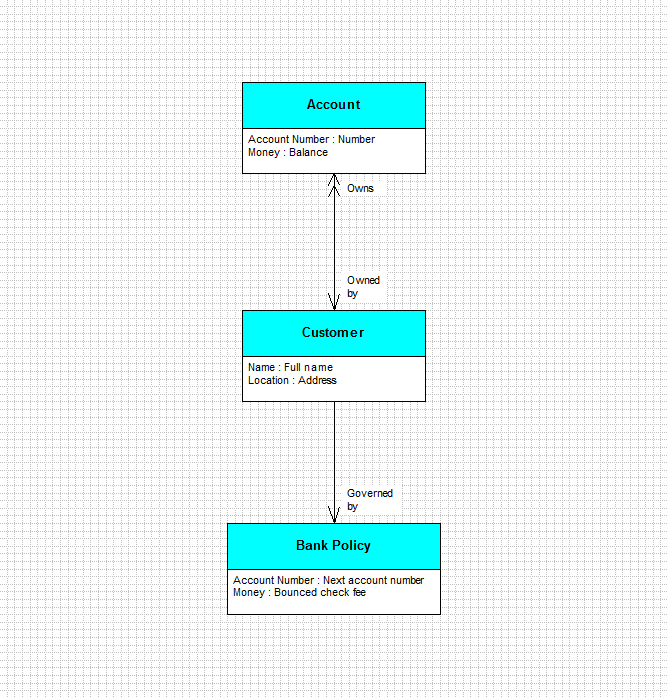
On the ERD, entities, attributes and relationships show abstractions from some part of the Real World or an imagined world. They enforce a naming convention for each subject area and using relational principles define precise details how entity objects are related.
State Transition Diagram (STD)
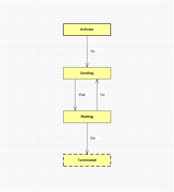
In Matrix, there are two kinds of entity, active and passive. A STD is a template that describes the state machine for all the objects that belong to an active entity. Passive objects do not have a STD.
In addition to naming the possible states that an object can take on, the STD also defines the events that the object must respond to with an associated change of state.
On entry to a new state, some processing may take place that will affect the system and the Real World.
Process Flow Diagram (PFD)
The PFD, which is the lowest level diagram, does not normally need to be drawn as the Matrix action code is a more precise and informative specification. Also, because the PFD is hard to maintain and keep consistent it should automatically be generated if and when required.
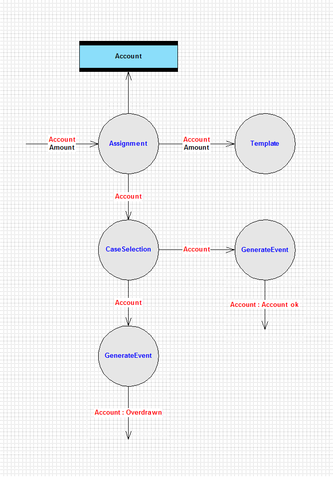
The diagram shows what is to be done on entry to a state by laying out processes and the control and data flows between them. Not all states on a STD need a PFD.
Here the processes have a one to one mapping with Matrix action statements, but this is not always the case.
The data on a flow is always determined by the requirements of subsequent process or processes.
There is always at least one transition flow in to the diagram and one process. A transition flow typically has an associated entity signifier (in red) and may also have state data (in black). A process may read or write into a data store and it may also generate an event.
Entity signifiers in red on data flows denote that the object's attributes and relationships are available. State data and process data are in black.
The GenerateEvent action process always produces an output flow which has a destination entity signifier that specifies the destination object (not creation events) and the name of the event generated (both in red). The flow may also have event data (in black) but no other entity signifiers are allowed.
A diagram showing just action processes is the lowest level PFD. Higher level PFDs may be created by combining process (levelling up).
|
||||||||||||||||||||||||||
|
|
||||||||||||||||||||||||||
| Copyright © 2017 Dark Matter Systems Ltd. All Rights Reserved. | ||||||||||||||||||||||||||
|
|
||||||||||||||||||||||||||
