 |
 |
|||||||||||||||||||||||||
|
Home : Matrix Language : Model Examples : Gothic Hotel Controller |
||||||||||||||||||||||||||
 |
||||||||||||||||||||||||||
|
Gothic Hotel Controller Model |
||||||||||||||||||||||||||
 |
||||||||||||||||||||||||||
|
Introduction
The Gothic Hotel Controller model is based on a description of an amusing but fantastical security system described by Martin Fowler of ThoughtWorks while discussing Domain Specific Languages (DSL)
A Matrix model version of the Gothic Hotel Controller
UML Diagram Notation Conversion
Unfortunately, the existing de facto UML notation is sub-optimal for Matrix analysis. Instead, the notation used in the Shlaer-Mellor method has been enhanced for use with the Matrix language. For completeness, the names of the Shlaer-Mellor diagrams have also been included in the table below:
Overview
In Matrix a DSL is defined as any custom language (textual or graphical) that populates a Matrix model. In other words, it is a language that produces object model configuration data for an executable model.
Arguments are presented that demonstrate the only role of a DSL is to populate an application's domain model and that there is no such thing as a "DSL model". The role of analysis and General Programming Languages (GPL) are also discussed.
Comments on Martin Fowler's Article
The article is about 7 years old at the time of review (article dated MON-27-SEP-2010). Only the first few sections of the article are relevant to the Matrix Gothic Hotel model example.
Domain-Specific Languages: An Introductory Example
1.1 Gothic Security
The author seems determined to model a state machine for reasons that are not entirely clear. He claims it "emerges" but then goes on to say "I should confess that originally in my writing it was the other way around. A state machine makes a good example for a DSL, so I picked that first".
It is simply not true to say that "a good way to think about the controller is as a state machine". Initially, it may appear a good choice but it quickly becomes clear this is not what the Problem Space is about.
It should be noted that state machines are a general purpose mechanism and universally useful modeling notation. There are few reasons to model a state machine; one of them is when modeling the Analysis of Analysis domain which is part of a Model Compiler.
In analysis, a controller entity (or God object) is not usually a thing that is modeled because its functionality is distributed amongst the various entities in the problem domain.
1.1.1 Miss Grant’s Controller
Miss Grant's secret panel has two unlocking sequences although it is clearly better security if only one is permitted.
Each unlocking sequence is independent but may coincidently share unlocking steps.
A sequence is simpler than a state machine. Mixing two or more sequences because they have common sections is not a valid reason to combine them in one state machine.
Indeed, combining several long unlocking sequences would reveal each one had an independent and separate path through the state machine.
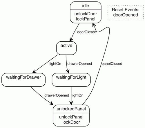
Miss Grant’s state diagram shows a specific example of two sequences. It is an example of a DSL in its own right. Each room would require another diagram showing different unlocking sequences.
The state diagram for Miss Grant’s secret compartment is actually at M0; this is the object level. You would expect to find a state machine diagram at M1, the entity level, in this context
M1 is the level at which an application analyst normally works. The meta-model level notation, M3, M2, M1 and M0 (also called the Four-Layer Architecture) was adopted by the OMG
M0 is the Real World object level, M1 is the analysis of the application model level (Analyst working level), M2 is the analysis of analysis meta-model level and M3 is the meta-meta-model level used to ensure all modeling notations defined at M2 are consistent. M3 is considered to be the highest and last meta level by the OMG and also by the original authors. In Matrix, it's not.
1.2 The State Machine Model
The author states "If people want to think about controller behavior with events, states, and transitions, then we want that vocabulary to be present in the software code too".
This is clearly wrong. If people want to think about controller behavior then they must think about things in the Problem Domain (Secret Panels, Unlocking Sequences etc.) not things in the Solution Domain (Events and States, etc.).
States, events, transitions and entities (UML classes) are concepts the analyst uses in order to express their design. These constructs do not belong in application code. They belong in the software architecture at the M2 level.
The class diagram of the state machine framework (Figure 1.2) is pitched at M1 model level. Normally this would be expected at the meta-model level M2 and is populated by the state diagram for Miss Grant’s secret compartment, M0 object level (Figure 1.1).
The code blocks in this section are a textual representation of the class diagram, M1 level of the state machine framework plus some behavior.
1.3 Programming Miss Grant’s Controller
The first code block in section 1.3 populates the class diagram of the state machine framework (Figure 1.2). It produces data at M0 for Miss Grant's controller. In Matrix, this code would be replaced by data configuration at the M0 level (Real World Objects).
The author highlights "separation of common code from variable code". In Matrix terms, "common code" is equivalent to the executable Matrix model and "variable code" to the object model configuration in data.
An alternative way of representing the configuration code is presented (second code block). XML is used to represent a data configuration. This is still consistent with the Matrix language Real World Objects realm.
The advantages of DSLs and of keeping the configuration data separate from the code are explained.
A third way of representing the configuration code is presented (third code block). But this time the newly invented "code" uses a custom syntax created for this example.
events doorClosed D1CL drawerOpened D2OP lightOn L1ON doorOpened D1OP panelClosed PNCL end
resetEvents doorOpened end
commands unlockPanel PNUL lockPanel PNLK lockDoor D1LK unlockDoor D1UL end
state idle actions {unlockDoor lockPanel} doorClosed => active end
state active drawerOpened => waitingForLight lightOn => waitingForDrawer end
state waitingForLight lightOn => unlockedPanel end
state waitingForDrawer drawerOpened => unlockedPanel end
state unlockedPanel actions {unlockPanel lockDoor} panelClosed => idle end
A new DSL is born.
The purpose of this DSL is to configure Miss Grant’s secret compartment state machine model (M1 level model) by populating the class diagram of the state machine framework (M2 level meta-model). This DSL replaces the need for Miss Grant's state machine model. Indeed, one should be reproducible from the other.
An internal DSL is not really a DSL in its own right. It is merely an external DSL that has been replicated in a general purpose language and therefore not very usable by the people who need to use it. However, an external custom DSL, either textual or graphical, forms a true DSL and would be crafted to be useful to an application domain expert not skilled in programming.
A fourth way of representing the configuration code is presented (fourth code block), this time using the Ruby language. Finally, a Java alternative is discussed (fifth code block).
1.4 Languages and Semantic Model
The author's distinction between domain models and semantic models is superfluous as far as Matrix is concerned because according to the author's definition all Matrix models are domain models.
A domain model is defined as a "behaviorally rich object model", whereas a semantic model is also an object model but does not specify behavior and is a data structure populated by semantic information from a DSL example. Drawing an object model is problematic since every Real World object must be represented separately on the diagram.
Matrix does not concern itself with object models but employs abstraction to build Matrix domain models that show and detail entities. Abstraction is the process by which problem space objects are examined and then grouped according to similar characteristics to extract entities and their attributes, relationships and life-cycles.
Matrix Model Walkthrough
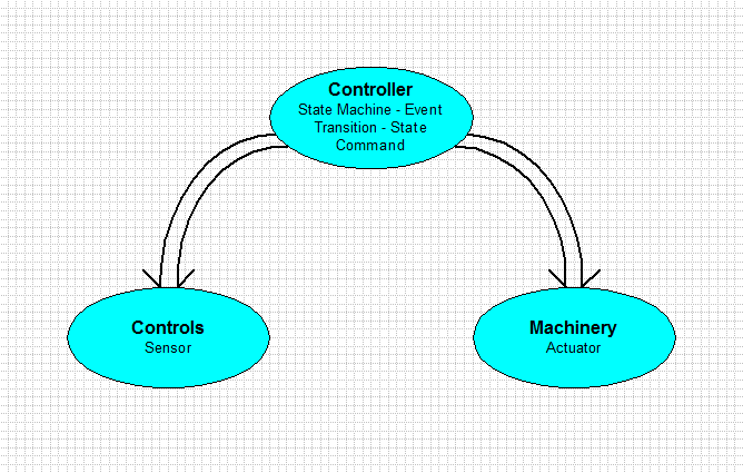
The Domain Bridge Diagram (DBD) below shows the top level application Controller domain and sets the system boundary for the model.
Normally, the entities contained by a domain model would be drawn from the Problem Space, but in this example the Controller is a domain model of a state machine and describes the components or entities that make up a state machine.
The Controls domain and the Machinery domain are interfaces to software and hardware that communicate to the Real World.
Realm: Analysis_Of_Application (Domains)
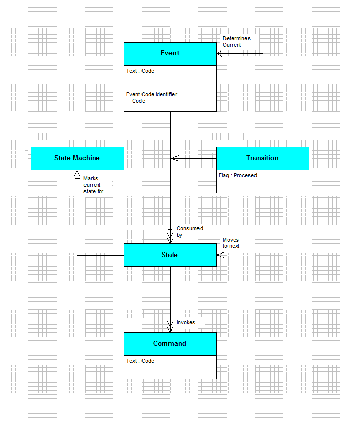
The Entity Relationship Diagram (ERD) below shows the relationships between the various entities in the Controller domain.
The entities are that of a simple state machine solely because the author chose the design.
Relationships can also represent state. It's ironic that the current state "variable" for the state machine is implemented as a relationship.
The notation used by the diagrams below is based on Shlaer-Mellor Method notation (similar to UML)
Domain: Controller
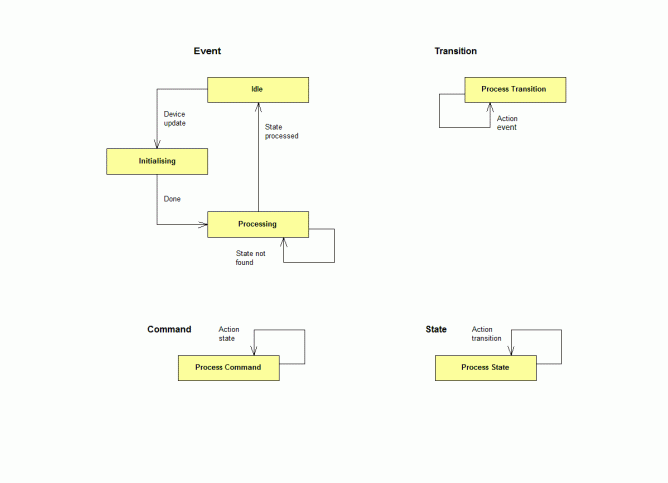
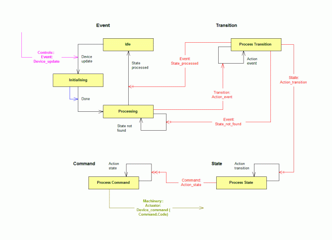
The Controller state machine is modeled using state machines.
The diagram below shows all the STDs from the Gothic Hotel Controller domain without showing how they interact. Click on the picture to get an expanded view of the diagram.
Domain State Transition Diagrams (Separate)
Click on the picture below to get an expanded view of the diagram showing the source of actual events and their destination among the collaborating entity STDs. An event based notation is used
Domain State Transition Diagrams (Annotated)
The Role of Domain Specific Languages
Typically, Matrix models are initiated or configured with data representing the starting state of the Real World objects in the system. The role of Domain Specific Languages (DSLs) within Matrix is to provide this configuration data which is used to populate the Matrix model. No more and no less.
A separate application, with a suitable graphical interface to the user, supplies the data in "raw" form to a model's M0 Silo.
The M0 Silo provides the complete dynamic state of the entire model frozen in time. This system starting point initializes the state machine in the Gothic Hotel Controller model.
The Matrix model initialization section, M0 Silo, is introduced by the following Matrix statements:
Silo:M0:Real_World_Objects RealmObject:Objects_Of_Analysis DomainObject:Controller
The EntityObject statement introduces an entity's objects, relations and events to be initialized. Matrix allows each object's attributes and initial state to be specified with the Object statement.
Additionally, it allows the object's relations to be given and this is achieved by assigning each object a unique identity. The identity is used in the ObjectRelation statement to match objects which take part in a relation. Only unary relations can be specified. Identities are only used to match object relations in the M0 Silo and do not appear in Matrix code. Neither are they are used in the code generation process.
Models can be made self-starting and self-initializing by defining initial events. The system's starting events may also be specified in this section with the ObjectEvent statement.
|-----------
EntityObject:Event Object | Identity | State | Code EVENT_DOOR_CLOSED : Idle : "D1CL" EVENT_LIGHT_ON : Idle : "L1ON" EVENT_DRAWER_OPENED : Idle : "D2OP" EVENT_PANEL_CLOSED : Idle : "PNCL" EVENT_DOOR_OPENED : Idle : "D1OP" ObjectRelation:Consumed_by:Transition EVENT_DOOR_CLOSED : EVENT_DOOR_CLOSED_STATE_IDLE EVENT_LIGHT_ON : EVENT_LIGHT_ON_STATE_ACTIVE EVENT_LIGHT_ON : EVENT_LIGHT_ON_STATE_WAITING_FOR_LIGHT EVENT_LIGHT_ON : EVENT_LIGHT_ON_STATE_WAITING_FOR_DRAWER EVENT_DRAWER_OPENED : EVENT_DRAWER_OPENED_STATE_ACTIVE EVENT_DRAWER_OPENED : EVENT_DRAWER_OPENED_STATE_WAITING_FOR_LIGHT EVENT_DRAWER_OPENED : EVENT_DRAWER_OPENED_STATE_WAITING_FOR_DRAWER EVENT_PANEL_CLOSED : EVENT_PANEL_CLOSED_STATE_IDLE EVENT_PANEL_CLOSED : EVENT_PANEL_CLOSED_STATE_ACTIVE EVENT_PANEL_CLOSED : EVENT_PANEL_CLOSED_STATE_WAITING_FOR_LIGHT EVENT_PANEL_CLOSED : EVENT_PANEL_CLOSED_STATE_WAITING_FOR_DRAWER EVENT_PANEL_CLOSED : EVENT_PANEL_CLOSED_STATE_UNLOCKED_PANEL EVENT_DOOR_OPENED : EVENT_DOOR_OPENED_STATE_ACTIVE EVENT_DOOR_OPENED : EVENT_DOOR_OPENED_STATE_WAITING_FOR_LIGHT EVENT_DOOR_OPENED : EVENT_DOOR_OPENED_STATE_WAITING_FOR_DRAWER EVENT_DOOR_OPENED : EVENT_DOOR_OPENED_STATE_UNLOCKED_PANEL
|-----------
EntityObject:Transition Object | Identity | State | Processed EVENT_DOOR_CLOSED_STATE_IDLE : Process_Transition : False EVENT_LIGHT_ON_STATE_ACTIVE : Process_Transition : False EVENT_LIGHT_ON_STATE_WAITING_FOR_LIGHT : Process_Transition : False EVENT_LIGHT_ON_STATE_WAITING_FOR_DRAWER : Process_Transition : False EVENT_DRAWER_OPENED_STATE_ACTIVE : Process_Transition : False EVENT_DRAWER_OPENED_STATE_WAITING_FOR_LIGHT : Process_Transition : False EVENT_DRAWER_OPENED_STATE_WAITING_FOR_DRAWER : Process_Transition : False EVENT_PANEL_CLOSED_STATE_IDLE : Process_Transition : False EVENT_PANEL_CLOSED_STATE_ACTIVE : Process_Transition : False EVENT_PANEL_CLOSED_STATE_WAITING_FOR_LIGHT : Process_Transition : False EVENT_PANEL_CLOSED_STATE_WAITING_FOR_DRAWER : Process_Transition : False EVENT_PANEL_CLOSED_STATE_UNLOCKED_PANEL : Process_Transition : False EVENT_DOOR_OPENED_STATE_ACTIVE : Process_Transition : False EVENT_DOOR_OPENED_STATE_WAITING_FOR_LIGHT : Process_Transition : False EVENT_DOOR_OPENED_STATE_WAITING_FOR_DRAWER : Process_Transition : False EVENT_DOOR_OPENED_STATE_UNLOCKED_PANEL : Process_Transition : False ObjectRelation:Consumed_by:State EVENT_DOOR_CLOSED_STATE_IDLE : STATE_IDLE EVENT_LIGHT_ON_STATE_ACTIVE : STATE_ACTIVE EVENT_LIGHT_ON_STATE_WAITING_FOR_LIGHT : STATE_WAITING_FOR_LIGHT EVENT_LIGHT_ON_STATE_WAITING_FOR_DRAWER : STATE_WAITING_FOR_DRAWER EVENT_DRAWER_OPENED_STATE_ACTIVE : STATE_ACTIVE EVENT_DRAWER_OPENED_STATE_WAITING_FOR_LIGHT : STATE_WAITING_FOR_LIGHT EVENT_DRAWER_OPENED_STATE_WAITING_FOR_DRAWER : STATE_WAITING_FOR_DRAWER EVENT_PANEL_CLOSED_STATE_IDLE : STATE_IDLE EVENT_PANEL_CLOSED_STATE_ACTIVE : STATE_ACTIVE EVENT_PANEL_CLOSED_STATE_WAITING_FOR_LIGHT : STATE_WAITING_FOR_LIGHT EVENT_PANEL_CLOSED_STATE_WAITING_FOR_DRAWER : STATE_WAITING_FOR_DRAWER EVENT_PANEL_CLOSED_STATE_UNLOCKED_PANEL : STATE_UNLOCKED_PANEL EVENT_DOOR_OPENED_STATE_ACTIVE : STATE_ACTIVE EVENT_DOOR_OPENED_STATE_WAITING_FOR_LIGHT : STATE_WAITING_FOR_LIGHT EVENT_DOOR_OPENED_STATE_WAITING_FOR_DRAWER : STATE_WAITING_FOR_DRAWER EVENT_DOOR_OPENED_STATE_UNLOCKED_PANEL : STATE_UNLOCKED_PANEL ObjectRelation:Moves_to_next:State EVENT_DOOR_CLOSED_STATE_IDLE : STATE_ACTIVE EVENT_LIGHT_ON_STATE_ACTIVE : STATE_WAITING_FOR_DRAWER EVENT_LIGHT_ON_STATE_WAITING_FOR_LIGHT : STATE_UNLOCKED_PANEL EVENT_LIGHT_ON_STATE_WAITING_FOR_DRAWER : STATE_IDLE EVENT_DRAWER_OPENED_STATE_ACTIVE : STATE_WAITING_FOR_LIGHT EVENT_DRAWER_OPENED_STATE_WAITING_FOR_LIGHT : STATE_IDLE EVENT_DRAWER_OPENED_STATE_WAITING_FOR_DRAWER : STATE_UNLOCKED_PANEL EVENT_PANEL_CLOSED_STATE_IDLE : STATE_IDLE EVENT_PANEL_CLOSED_STATE_ACTIVE : STATE_IDLE EVENT_PANEL_CLOSED_STATE_WAITING_FOR_LIGHT : STATE_IDLE EVENT_PANEL_CLOSED_STATE_WAITING_FOR_DRAWER : STATE_IDLE EVENT_PANEL_CLOSED_STATE_UNLOCKED_PANEL : STATE_IDLE EVENT_DOOR_OPENED_STATE_ACTIVE : STATE_IDLE EVENT_DOOR_OPENED_STATE_WAITING_FOR_LIGHT : STATE_IDLE EVENT_DOOR_OPENED_STATE_WAITING_FOR_DRAWER : STATE_IDLE EVENT_DOOR_OPENED_STATE_UNLOCKED_PANEL : STATE_IDLE
|-----------
EntityObject:State Object | Identity | State STATE_IDLE : Process_State STATE_ACTIVE : Process_State STATE_WAITING_FOR_LIGHT : Process_State STATE_WAITING_FOR_DRAWER : Process_State STATE_UNLOCKED_PANEL : Process_State ObjectRelation:Marks_current_state_for:State_Machine STATE_IDLE : STATE_MACHINE ObjectRelation:Invokes:Command STATE_IDLE : LOCK_PANEL STATE_IDLE : UNLOCK_DOOR STATE_UNLOCKED_PANEL : LOCK_DOOR STATE_UNLOCKED_PANEL : UNLOCK_PANEL
|-----------
EntityObject:Command Object | Identity | State | Code LOCK_DOOR : Process_Command : "D1LK" UNLOCK_DOOR : Process_Command : "D1UL" LOCK_PANEL : Process_Command : "PNLK" UNLOCK_PANEL : Process_Command : "PNUL"
|-----------
EntityObject:State_Machine Object | Identity STATE_MACHINE
It should be possible, using a bi-directional model-to-model transformation, to reproduce the source DSL code from the M0 Silo data (textual or graphical but obviously without the graphical layout information).
Conclusion
The disadvantages of the state machine controller design are clear:
When analysing any problem always look for the entities in that problem. Do not decide on a mechanism beforehand and then try to describe the problem in terms of that mechanism.
In Matrix, the knowledge of how the problem is "solved" is exposed in the form of an executable model. The purpose of a DSL is to populate this existing domain model. DSL tools often obfuscate this purpose by adding functionality that provides a level of analysis capability and some code generation.
External DSLs are the real DSLs. This is because only external DSLs are likely to be understood by users who don't know how to program general programming languages. These are experts in their own subject matter who will configure existing models for their own situation.
Matrix Model
The Matrix (Professional Edition) of the Gothic Hotel Controller model is available
Expected Output
The output from the Matrix version of the Gothic Hotel Controller model executing a short scenario is available |
||||||||||||||||||||||||||
|
|
||||||||||||||||||||||||||
| Copyright © 2017 Dark Matter Systems Ltd. All Rights Reserved. | ||||||||||||||||||||||||||
|
|
||||||||||||||||||||||||||


